
Induction type non-directional over current relay
This Induction Type Overcurrent Relay works on the induction principle and initiates corrective measures when current in the circuit exceeds the predetermined value. The actuating source is a current in the circuit supplied to the relay from a current transformer. These relays are used on a .c. circuits only and can operate for fault current flow in either direction.
Constructional details: fig shows the,important constructional details of a typical non-directional induction type overcurrent relay. It consists of a metallic (aluminium) disc which is free to rotate in between the poles of two electromagnets. The upper electromagnet has a primary and a secondary winding. The primary is connected to the secondary of a C.T. in the line to be protected and is tapped at intervals. The tappings are connected to a plug-setting bridge by which the number of active turns on the relay operating coil can be varied, thereby giving the desired current setting. The secondary winding is energized by induction from primary and is connected in series with the winding on the lower magnet. The controlling torque, is provided by a spiral spring.
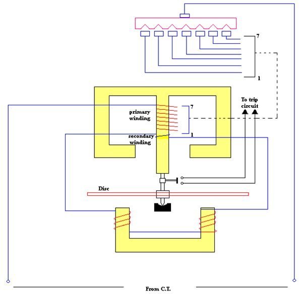
The spindle of the disc carries a moving contact which bridges two fixed contacts (connected to trip circuit) when the disc rotates through a pre-set angle. This angle can be adjusted to any value between 0° and 3600. By adjusting this angle, the travel of the moving contact can be adjusted and hence the relay can be given any desired time setting.
Operation: The driving torque on the aluminium disc is set up due to the induction principle. This torque is opposed by the restraining torque provided by the spring. Under normal operating conditions, restraining torque is greater than the driving torque produced by the relay coil current, Therefore, the aluminium disc remains stationary. However, if the current in the protected circuit exceeds the pre-set value, the driving torque becomes greater than the restraining torque. Consequently, the disc rotates and the moving contact bridges the fixed contacts when the disc has rotated through a pre-set angle. The trip circuit operates the circuit breaker which isolates the faulty section.
Pick up current :
It is the minimum current in the relay coil at which the relay starts to operate. If the current through the Relay coil is less than the pick-up value then Relay won’t operate. On contrary, if the current through the Relay coil is more than the Pick-up current, Relay will operate.
Current setting:
It is often desirable to adjust the pick up current to any required value. This is known as current setting and is usually achieved by tappings on the relay operating coil…Suppose we are using a CT of ratio 1000/1 A and the pick-up current needs to be set at 1.2 A. Then we will simply put the plug provided on relay coil to 120% or 1.2.
Pick up current = rated secondary current of CT X Current settings
Plug setting multiplier (PSM).
Plug Setting Multiplier (PSM) is defined as the ratio of fault current to the pick-up current of the relay.
PSM = Fault Current / Pick-up Current
= Fault Current / (Plug Position x Rated CT Secondary Current)
Suppose we are using CT of 100/1 A, a fault current of, say 5000 A is flowing through the network protected by the relay.
Fault current in CT secondary = (5000×1) / 100 = 50 A
Assume that Current Setting or the position of plug is at 5 then
PSM = 50 / (1×5) =10
Time Setting Multiplier (TSM):
A Relay is generally provided with control to adjust the time of operation of the Relay. This adjustment is known as Time Setting Multiplier or TSM.


Recent Comments